TG8Ex Series ATEX zone II

The temperature sensors TG8Ex are designed to meet the requirements of EN 60079-0:2013+A11:2014, EN 60079-7:2016 and EN 60079-31:2014, as amended. Sensors marked on the nameplate with II3G Ex ec IIC T6…T2 Gc and II3D Ex tc IIIC T60°C…230°C DC can be used in potentially explosive environments – Equipment Group II, Zone 2 and Zone 22.

The sensors operate on the principle of defined dependency of the change of property of the sensor and the change of temperature. They are not capable of generating sparks, arcs, or high surface temperatures. The temperature range for use in potentially explosive environments is limited by the insulation of the cable used and specifically specified in the operating instructions – the specified measuring range must not be exceeded, even for a brief period. The supply cable may have an outer PVC, silicone, or PTFE (Teflon) insulation and may be either shielded or unshielded. According to EN 60 529, as amended, the sensors meet IP 65 in the case of PTFE (Teflon) cable insulation and IP 67 in the case of other supply cables.
The sensors are designed to be operated in a chemically non-aggressive environment, the use must be chosen regarding the temperature and chemical resistance of the case and the supply cable.

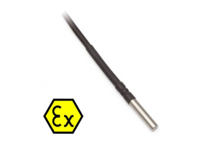
Series TG8Extemperature sensors – In combination with the JTG8 thermowell or central holder, supplied as accessories, the sensors can be used for temperature measurement of gaseous and liquid substances in piping or air conditioning ducts or separately for temperature measurement of solids. They consist of a metal measuring case with a diameter of 5.7 mm, 6 mm, 7 to 10 mm or 12 mm, which contains a temperature sensing element and supply cable. The metal sensor case can be made of stainless-steel DIN 1.4301, DIN 1.4404, DIN 1.4571. The wiring of the sensors can be 2-wire, 3-wire or 4-wire. In the case of shielded supply cables, the shielding is not connected to the case or to the temperature sensing element. The case length can be selected from the range of 40 to 400 mm, depending on the sensor case diameter.

Specification

Sensor type TG8Ex
Standard types of sensing elements* all types (Pt 100, Pt 1000, Ni 1000, Ni 10000,Ni 2226=T1, NTC, PTC, KTY, TSiC, DALLAS, TC K, TC J, TC T and so on)
Measuring range Y -- T2: - 40 ≤ Ta ≤ 230 °C cable PTFE(teflon)
T3: -30 ≤ Ta ≤ 180 °C cable SILICONE
T5: -20 ≤ Ta ≤ 95 °C cable PVC up to 105 °C
T6: - 20 ≤ Ta≤ 60 °C cable PVC
Recommended / maximum DC measuring current 1 mA / 3 mA for the sensors with sensing element Pt 100
0.5 mA / 1.5 mA for the sensors with the sensing element Pt 500
0.3 mA / 0.8 mA for the sensor with the sensing element Pt 1000
0.3 mA / 1 mA for other sensors
Recommended / maximum DC power consumption of sensing element 0.05 mW / 1 mW for the sensors with the sensing element NTC 20 kΩ
Accuracy class Ni sensing elements: B class, Δt = ± (0.4 + 0.007t), for t ≥ 0; Δt = ± (0.4 + 0.028|t|), for t ≤ 0 in °C;
Pt sensing elements: B class according EN 60751, Δt = ± (0.3 + 0.005|t|) in °C
NTC 20 kΩ: ± 1 °C for the range 0 °C to 70 °C
Sensor connection 2-wire, 3-wire, 4-wire
Insulation resistance min. 200 MΩ at 500 V DC, at the temperature 15 °C to 35 °C, maximum rel. humidity 80 %
Dielectric strength (ATEX) 1 000 V DC during the period 1 s, at the temperature 15 °C to 35 °C, maximum rel. humidity 80 % according to the article 6.8.1. of the EN 60079-15 ed. 2 standards, as amended
Ingress protection IP 67 for cables with PVC and SILICONE-insulation in accordance with EN 60529, as amended
IP 65 for cables with PTFE (teflon) insulation in accordance with EN 60529, as amended
Types of lead-in cables and their thermal resistivity -50 to 200 °C MCBE-AFEP, 2 x 0.34 a 4 x 0.15 mm2, silicone insulation
-40 to 105 °C FLRYWYW, 2 x 0.35 a 4 x 0.35 mm2, PVC insulation up to 105 °C
-30 to 80 °C LiYCY 2 x 0.34 mm2, PVC uninsulated
-50 to 260 °C PTFE insulation
Weight according to the length of the cable, minimum 0.15 kg
Stem length 40 to 400 mm
Stem diameter 5.7 mm, 6 mm, 7 to 10 mm, 12 mm
Material of the stem stainless steel DIN 1.4301, DIN1.4571, DIN 1.4404
Time response τ0,5 ≤ 5 s, τ0,9 ≤ 12 s for stem ⌀ 5.7 mm
τ0,5 < 9 s, τ0,9 ≤ 20 s for stem ⌀ 6 mm
τ0,5 < 14 s, τ0,9 ≤ 35 s for stem ⌀ 7 to 8 mm
τ0,5 < 25 s, τ0,9 ≤ 60 s for stem ⌀ 9 to 10 mm
τ0,5 < 35 s, τ0,9 ≤ 80 s for stem ⌀ 12 mm

*) Certain technical specifications of thermocouple sensors (lead wires, IP rating, etc.) may differ with different types.
Note: Manufacturer reserves the right to make changes in design and technical characteristics of the products. For actual information, please always contact your dealer.

Dimensional Draft

Wiring Diagram

Visit our downloads page to view technical characteristics or contact our technical sales department for more information, prices or with your specifications.

Also, you can reach us on +44 (0) 1865400514
We use cookies to deliver you the best experience. By browsing our website you agree to our use of cookies. Learn More